|
Choosing the correct blower is a fundamental step in designing a functional and efficient system. We’ve covered the basics of Regenerative versus Centrifugal Blowers and Understanding Blowers as part of System, in this article we’ll show how to read a blower curve and use that information to specify the best blower for your project.
Most blower suppliers use similar types of specifications to describe the blower function. Below is an example of a typical blower spec sheet.
Pressure and Air Flow
The two most important variables used in system design are pressure and air flow.
For impeller based centrifugal and regenerative blowers there is an inverse relationship between air flow and pressure at the blower outlet. This means that increasing the system back pressure on the blower outlet will result in a decreasing volumetric air flow rate.
The table above states the maximum pressure and maximum volumetric flow rate. For smaller blowers, this maximum pressure is where the flow output goes to zero; for larger blowers, this is the maximum sustainable continuous operating pressure for the unit. The maximum air flow is the output when the pressure at the outlet is zero (I.E. when the blower is venting directly to atmosphere). It is important to understand that these are maximum values and not the performance that should be expected under normal operating conditions. The pressure at the blower outlet is the cumulative pressure caused by any elements connected that resist flow. Elements such as length or path of hose or pipe, nozzles, and inline heaters will all contribute to the amount of back pressure the blower must overcome. Read more about back pressure in our article Understanding Blowers as part of System. The greater the back pressure exerted on the blower, the lower the amount of flow that the blower can supply. At the extreme end, if the outlet of the blower is completely blocked there will be zero air flow. If a blower is venting directly to atmosphere (i.e., there are no system elements connected) it will be capable of its maximum rated flow capacity. A blower manufacturer will supply a blower curve for each blower type which describes the relationship between pressure and flow for that particular model. 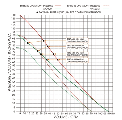
Frequency
In the above example there is a set of curves for each 50Hz and 60Hz. This is often the case since the same blower is manufactured for use around the world. The rotational speed of a blower increases with increasing operating frequency; as a result the output of the blower is increased as well. Therefore the 60Hz blower curves are shifted further to the right on the chart than the 50Hz curves. See our article on Variable Frequency Drives for more explanation on how frequency can affect a blower.
Pressure vs. Vacuum
Blowers consist of an inlet where air is drawn in and an outlet where air is expelled. They can be used to either create pressure at the outlet or create a vacuum at the inlet. Because blowers are commonly used for both functions, a blower curve may describe both situations as seen in the example above.
Continuous Operation Limits
A blower curve shows the characteristics of the blower through its entire operating range. However, operating a blower above its maximum pressure continuously will severely limit its lifespan. For this reason manufacturers include the pressure limit where a blower can safely operate for long periods of time. In the example above, the manufacturer has a line of blowers with the same blower curve but with different continuous operation pressure capabilities.
If continuous operation limit points are not supplied on a blower curve it is best to select a blower such that it is working in the mid-range of its capability. For example, on the above curve if the desired operating pressure is around 50 to 60 inches of water we can only expect approximately 50 CFM of flow. This is less than half of the 106 CFM maximum capacity stated in the table. It is important to choose a blower based of the actual flow required for the system as opposed to the maximum capacity rating in order to prevent the blower from failing prematurely or just being a poor fit for the application. When researching blower options, be sure you’re given all of the information you need; if not, ask! Make sure you get a blower curve and not just the top line specifications so you can make a well-informed decision. If you are not sure what you should be looking for call us and we can help step you through the choices to be sure you get exactly what you need. Originally published: 05/16/2014 Comments are closed.
|

|
STANMECH Technologies Inc.
944 Zelco Drive Burlington ON L7L 4Y3 | 1-888-438-6324 | [email protected] Terms of Use Privacy Terms and Conditions of Sale Warranty Policies |
|
Proud Member of: