The practical application of blower curves
How a blower will function once it is connected to other components is often misunderstood, which can result in the selection of the wrong tool for an application. In previous articles we have discussed the differences between centrifugal and regenerative blowers, how to interpret blower curves, and the differences between flow, velocity, and pressure. This article expands on these topics with a practical case that shows how these concepts interconnect.
When looking at a list of specifications for a blower you will find values for the Maximum Volumetric Flow Rate and Maximum Operating Pressure. While this is good information to have when selecting a blower, in most cases, it is not nearly enough information to predict the blower’s performance once it is part of a system. Pressure Drop: A Key Piece of (Often) Missing Information
When designing a blower-based system, it is important to understand the concept of pressure drop, how it affects blower performance, and how system design affects it. Pressure drop is the difference in pressure from one point in a system to another. When sizing a blower for a system, the most important pressure drop to consider is from the outlet of the blower to the end of a system (usually where it vents to the atmosphere). This is often referred to as the back pressure on the blower, or the operating pressure of the blower.
Any component added to the outlet side of the blower increases this cumulative pressure. For example:
Blower Curves: Where Flow meets Pressure
The maximum volumetric flow rate listed in most blower specifications is the flow rate when there is zero pressure applied on the blower outlet; this is typically only seen when the blower is venting directly to the atmosphere as is rarely the case in real-world situations. As soon as back pressure is applied to the blower the flow rate decreases. This is an inverse relationship, meaning that the flow rate decreases further with increasing back pressure on the blower. This relationship is modeled in a blower curve. Each individual blower model will have a unique blower curve.
For more information about reading blower curves see our article How to Interpret a Blower/Fan Curve. Blower Selection: A Practical Example
To understand this more clearly, consider the following simplified, practical scenario: An industrial process requires a pre-heating stage utilizing hot air. After conducting some initial heat calculations it has been determined that approximately 15kW of heat is required. Due to application constraints, we cannot inject air into the process above 450°C. After a review of the heaters available, the Leister LHS 61L SYSTEM 16kW heater has been selected for the application. It is now time to select a suitable blower to pair with this heater. Consulting Leister’s recommended combination possibilities for this heater narrows the available options to the Leister AIRPACK and the Leister ASO blowers. The AIRPACK is a regenerative blower with a maximum airflow of 3900 L/min (operating at 50 Hz), while the ASO is a centrifugal blower with a maximum airflow of 13500 L/min (operating at 50 Hz). Supplied with this information alone it would appear that the Leister ASO will supply significantly more airflow for this application, however, this would be an incorrect assumption! 
According to Leister’s combination possibilities chart, when the selected heater is used at full power with an ASO blower you should expect an approximate flow rate and output temperature of 1500 L/min at 610°C; when this heater is used at full power with an AIRPACK blower you should expect an approximate flow rate and output temperature of 3450 L/min at 360°C. This is the result of the back pressure caused by the addition of the heater and hose to the blower outlet.
With this additional information we can see that the AIRPACK is the best choice for this application, as when used with the heater it will be able to supply the necessary 15kW of heat at a temperature below the 450°C input limit. Whereas in order to use the ASO with this heater we would have to reduce the output power percentage from the heater to satisfy the 450°C input constraint and in doing so would fall short of the 15kW required by the process.
A frequent assumption is that if a blower has a higher specified flow rate it will have a higher flow rate once in use, however, this is not always the case as seen above.
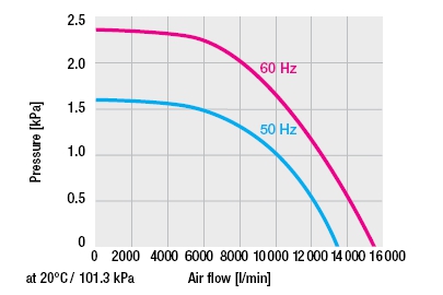
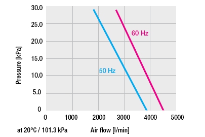
With our new knowledge about blower curves, let’s investigate further what is happening. First, please see the blower curves for the Leister ASO and AIRPACK below.
Blower Curves for the Leister ASO (left) and the Leister AIRPACK (right)
The Leister ASO has a much higher flow rate when there is zero back pressure, but this flow rate drops off much more rapidly than the AIRPACK as back pressure is increased. The AIRPACK starts with a much lower flow rate than the ASO when there is zero back pressure, but a back pressure of 1.5 kPa that would reduce the flow rate of the ASO to almost zero (at 50 Hz) has almost no impact on the flow rate of the AIRPACK!
From this information we can infer that the Leister heater mentioned in the scenario imparts a significant amount of back pressure on a blower, especially at elevated flow rates and temperatures. This back pressure has less of an impact on the AIRPACK blower as it is a regenerative blower and is less sensitive to this back pressure than the ASO which is a centrifugal blower. For more information about blower types, see our article Regenerative versus Centrifugal Blowers. We hope that this has increased your knowledge of how blowers interact with the system in which they are installed. Please call us if you would like to further discuss your specific application. *NOTE: The information contained in this article applies to Centrifugal and Regenerative style blowers. There may be other blower designs for which this information does not hold. Comments are closed.
|

|
STANMECH Technologies Inc.
944 Zelco Drive Burlington ON L7L 4Y3 | 1-888-438-6324 | [email protected] Terms of Use Privacy Terms and Conditions of Sale Warranty Policies |
|
Proud Member of: