|
In a previous article, Temperature Control of Air Heaters, we provided a general overview of control for process heat systems and explained the difference between closed- and open-loop controls. Briefly, a closed-loop system is output driven; the output of the system is continually measured and fed back to control components which adjust the operation of the tool to bring its output into alignment with a pre-set target. An open-loop system has no feedback loop and, as a result, the output of the tool does not impact its continued operation. For example, in a closed-loop process heat system if the inlet air increases in temperature the tool output temperature will briefly increase before the control system brings it back to set point, however in an open-loop system the tool output temperature will increase and no corrective action will occur.
In this article series we will expand on this topic, exploring when it is advantageous to use a closed-loop system and when it is acceptable to use an open-loop system. This first installment will look at the benefits of automating your system with closed-loop control and the process issues that this can help resolve. Process Precision
If your application has tight tolerances and temperature requirements, then it will likely require a closed-loop control system. Including a feedback loop in your control scheme will ensure that you are getting the temperature you need, where you need it. Closed-loop control greatly increases the accuracy of a process heat system as the output is constantly being measured and adjustments are being made when necessary to keep the output on target.
A heat/shrink tunnel, is an enclosed and heated area that is used to not just apply heat to an object, but create a heated local environment around said object. Heat tunnels are generally found above or enveloping a section of conveyor belt to allow for automated travel through the tunnel. The most common use for a heat tunnel is the activation of heat shrink labels, packaging, and tamper bands on a container; however, they are also used to cure paints and heat parts. This article series will cover the most common types of heat tunnels available, their advantages and disadvantages, and the technical complications of heat shrinking. Be sure to read parts one and two of this series before proceeding.
Technical Complications of Heat Shrinking
For the majority of applications, applying a shrink label to packaging is not as straightforward as simply passing the container through an off-the-shelf heat tunnel. There are a multitude of factors that complicate the heat shrinking process. Taking time to consider these factors is important to designing a successful and robust system.
Shrink Label Material
The most common shrink materials are PVC, PETG, and PLA. The choice of material can greatly change the requirements for, and effectiveness of, a heat tunnel. These materials shrink because, during manufacturing, they are stretched until their polymer chains are almost aligned; this is an unnatural state. When heat is applied these materials revert to their natural, tangled state resulting in their shrinking.
PVC tends to be the cheapest and easiest material as it shrinks at a lower temperature and more evenly when heat is applied. PVC typically has an amorphous structure which means that it shrinks uniformly without localized areas of distortion and is less likely to wrinkle. It also has good scuff resistance. However, PVC is less environmentally friendly than other plastics and will contaminate recycling streams when mixed with dissimilar plastics.
A heat/shrink tunnel, is an enclosed and heated area that is used to not just apply heat to an object, but create a heated local environment around said object. Heat tunnels are generally found above or enveloping a section of conveyor belt to allow for automated travel through the tunnel. The most common use for a heat tunnel is the activation of heat shrink labels, packaging, and tamper bands on a container; however, they are also used to cure paints and heat parts. This article series will cover the most common types of heat tunnels available, their advantages and disadvantages, and the technical complications of heat shrinking. Be sure to read part one of this series before proceeding.
Advantages and Disadvantages
Most technologies have ideal areas of application which relate directly to their strengths and weaknesses. The following is a summary of the strengths and weaknesses of the three types of heat tunnels discussed.
Infrared Tunnels
Advantages
We've written previously about the Advantages of a Screw Extruder for Extrusion Plastic Welding. In a screw-based extruder, the turning screw grinds up the welding rod as it passes through the barrel. Both the mechanical energy of the turning screw and heat introduced along the extrusion barrel plasticize the incoming material. The barrel can be heated either with hot air or with a coil heater.
Screw Extruder with Hot Air Heating (e.g., FUSION)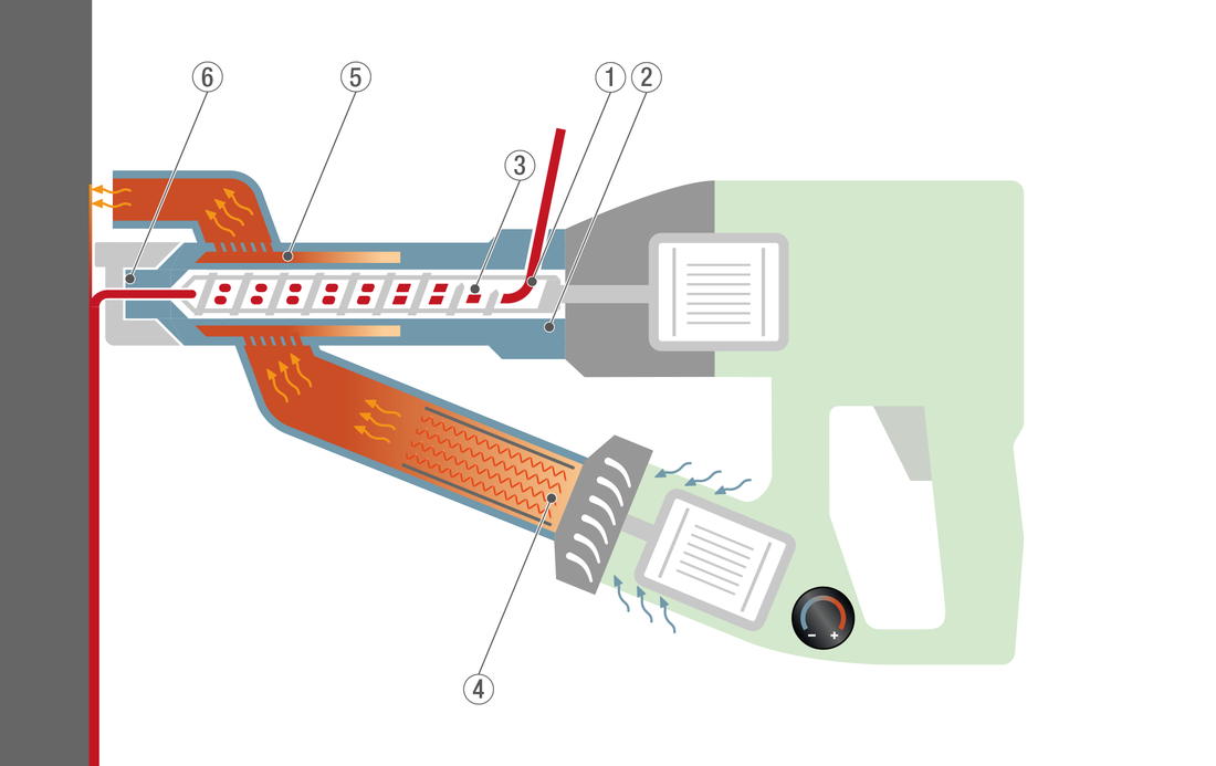
Principle of Screw Extruders with Hot Air Heating
A heat/shrink tunnel, is an enclosed and heated area that is used to not just apply heat to an object, but create a heated local environment around said object. Heat tunnels are generally found above or enveloping a section of conveyor belt to allow for automated travel through the tunnel. The most common use for a heat tunnel is the activation of heat shrink labels, packaging, and tamper bands on a container; however, they are also used to cure paints and heat parts. This article series will cover the most common types of heat tunnels available, their advantages and disadvantages, and the technical complications of heat shrinking.
Types of Heat Tunnels
The type of heat tunnel is determined by the heat source used. Common heat sources include infrared, steam, and hot air. Regardless of the type, all heat tunnels work by transferring energy from a heat source to an object within an enclosed area. The goal may be to a shrink film/label, cure a coating of paint, remove excess water/moisture, or any other application requiring immersion in heat but the principals remain the same. The amount of energy transferred depends on the output capacity of the heat source, the material being heated, and the residence time of the object in the tunnel.
A welding rod, as recommended by the manufacturer, must be used when installing linoleum, rubber, PVC, or TPU surfaces. Welding rods are generally available with 3 to 5 mm diameters. Speak with your material manufacturer or supplier to find out more.
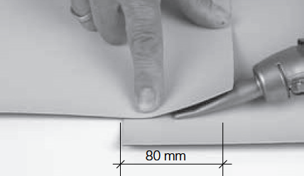
Before welding, the seam edges must be milled or grooved to approx. 2/3 of the thickness of the material. The welding rod is then welded into the groove to create a strong bond. It is important that the welding rod fully penetrates the milled groove otherwise the seam may fail prematurely. The welding rod is then trimmed in two stages: The first pass is done with a trimming guide immediately after welding. This removes the bulk of the excess rod. The second pass is done once the material has cooled completely. This helps prevents concave seams, producing an even, flush seam with a long service life. Substrate Properties
A properly prepared substrate should be solid, evenly laid, and free from debris such as loose screws or stones. Rain If it is raining, welding must not be carried out without special protective equipment. Air Temperature Welding must be suspended at temperatures below +5°C in order to prevent the material from being exposed to an excessively high thermal load (in accordance with DVS 2225-4). Humidity In some cases, excessively high humidity can cause condensation to form on the welding surface, which has a negative effect on seam strength. Wind If there is strong wind, the tool may not reach the required welding temperature. This can be counteracted by raising the welding temperature by 20 to 30°C or reducing the speed by 20 to 40 cm/min. If the wind is excessively strong, the welding area should be shielded against wind or welding should be suspended. Sun Prolonged exposure to the sun can cause the material to heat up significantly causing thermal expansion. This causes wrinkles which makes the welding process more difficult and leads to an unacceptably high level of tension in the seam area when the material cools. Maintaining the Tools The air inlet and filter should be cleaned frequently and the heating element removed and cleaned periodically. This ensures the tool is able to produce the correct air volume and temperature output. Using Generator Power The generator must have the correct specifications in order to ensure safe operation:
Manual Welding Process
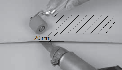
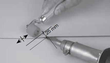
The distance between the pressure roller and the nozzle opening should be between 20 and 30 mm to ensure that the weld seam is joined as efficiently as possible. The pressure roller must be guided so that it is parallel to the nozzle. This will ensure that the welding process yields the best possible results (see images above).
The hot-air nozzle should be cleaned periodically to keep the contaminants out of the welding seam. A blocked nozzle will restrict the tool’s air output which may cause fluctuations in the output temperature. Large format printing of banners can produce a stunning final product. Very large banners require the joining of two or more pieces of material by welding, stitching, or gluing. When welding two banner pieces together the type of ink used becomes an important consideration.
Solvent-based inks cannot be welded. The ink interrupts the bonding process. Instead, leave a margin unprinted on the banner the width of the required weld. Be sure to carefully align the pieces of material to make sure the final product is perfect. Water-based inks can be welded without issue, no margin need be left when printing. Have questions about your material? Give us a call. The new HEMTEK stationary welder from Leister is easy to use, see how in this video: |

|
STANMECH Technologies Inc.
944 Zelco Drive Burlington ON L7L 4Y3 | 1-888-438-6324 | info@stanmech.com Terms of Use Privacy Terms and Conditions of Sale Warranty Policies |
|
Proud Member of: