STANMECH Technologies Inc.
  • Home
  • Equipment Supply
    • Flooring
    • Geomembrane
    • Industrial Fabrics
    • Manufacturing
    • Plastic Fabrication
    • Roofing >
      • Distributors
  • Engineering Services
    • Engineering Services
    • Cosmetics
    • Deflashing Systems
    • Drying Bottles & Cans
    • Heat Systems
    • Shrinking Labels
  • Repair
    • Repair Service
    • Tech Tips
  • Resources
    • Articles
    • Case Studies
    • Engineering Information
    • Whitepapers
  • About
    • About Us
    • Technology Providers
  • Contact

Thermocouples in Hot Air Systems

9/20/2019

 
HOTWIND how air blower with thermocouple
Thermocouples are widely used to measure temperature in industrial processes. In this article we will explain how a thermocouple works, when you should use one, and some best practices for use.

How does a thermocouple work?

Thermocouple
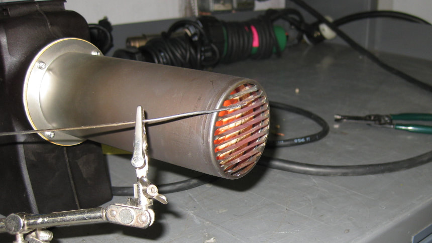
A thermocouple consists of two different conducting metals joined at one end and uses the Seebeck effect to measure temperature. The Seebeck effect is where a conductor will generate a voltage when subjected to a temperature gradient. By using dissimilar metals the Seebeck effect will result in a measurable generated voltage at the unjoined end of the thermocouple which can then be converted to a temperature reading using specialized calibrated equipment such as a temperature controller or thermocouple meter. 

There are several types of thermocouples which couple different conductors, this gives different measurement characteristics to each type. The most common types are J, K, T and E. The choice of thermocouple type depends firstly on the temperature range required and then on the operating environment.

There are some good sources for more detailed information on thermocouples in the “Further Reading” section at the end of this article.

When should you use a thermocouple?

A thermocouple can be used whenever a temperature either needs to be displayed or controlled but there are other options that could be considered: RTDs and Thermistors.

Both RTDs and Thermistors use a material change in resistance with temperature as the basis for temperature sensing. RTDs use a metal wire wrapped around a core or embedded in a thin film and thermistors use semiconductor material. The table below shows a comparison of the performance of three types of devices; devices are ranked from 1 to 3 with 1 being the best option for each criteria.
Thermocouple RTD Thermistors
Cost 1 3 2
Robustness 1 2 3
Sensitivity 3 2 1
Range -250 to 2300 -240 to 600 -100 to 500
Stability 3 1 2
Response Time 1 3 1
At STANMECH we largely use thermocouples. This is because our applications generally require a robust device that can withstand industrial processes, the higher temperature range, and the cost. For our applications the additional sensitivity and stability offered by RTDs and thermistors are not required as the accuracy that can be achieved with hot air is within the capability of thermocouples.

Thermocouple Best Practices

  • When using a thermocouple for temperature feedback in a control system, remember that thermocouple placement effects control effectiveness.
    • A thermocouple placed a long distance from the heat source will cause time delays and decrease accuracy on the control system.
    • Place the thermocouple as close to the critical temperature point as possible. If it is critical that the part must be maintained at a certain temperature it makes sense that the thermocouple should be near the part so that the temperature being controlled is the right one.
  • Be sure that you are using the right type of thermocouple. As mentioned previous there are different types of thermocouples (J, K, etc.). Each type also comes in several configurations that affect the sensitivity and response time. The choice depends on the application.
  • Be sure that your thermocouple wire is compatible with the type of thermocouple you are using. Mismatching thermocouples and thermocouple wire will throw off the calibration of the device connected to read the temperature.
  • There is a limit to the distance you can have between the thermocouple and the measuring device before the added resistance causes problems. If you require a long run check with your thermocouple manufacturer for limitations.
  • There is potential for signal interference, especially with long cable runs. This can be minimized by choosing the right cable screening or thermocouple cable type.

Further Reading

OMEGA Engineering Technical Reference: Introduction to Thermocouples
National Instruments: How to guide for most common measurements

Originally published: 4/17/2015

Comments are closed.

    Index by Industry

    Flooring Installation
    Geomembrane Welding
    Industrial Fabrics Welding
    Manufacturing
    Plastic Fabrication
    Roofing

    Browse Newest

    All
    Engineering Services
    Flooring Installation
    Geomembrane Welding
    Industrial Fabrics Welding
    Manufacturing
    Plastic Fabrication
    Roofing
    Video

      Comments & Questions

    Submit
STANMECH Technologies Inc. 
​944 Zelco Drive Burlington ON L7L 4Y3 | 1-888-438-6324 | info@stanmech.com
Terms of Use    Privacy    Terms and Conditions of Sale    Warranty Policies 
Français

Proud Member of:
IFAI Logo
Industrial Fabrics Association International
IAGI Logo
International Association of Geosynthetic Installers
PEO Logo
Authorized by the Association of Professional Engineers of Ontario to offer professional engineering services. 
  • Home
  • Equipment Supply
    • Flooring
    • Geomembrane
    • Industrial Fabrics
    • Manufacturing
    • Plastic Fabrication
    • Roofing >
      • Distributors
  • Engineering Services
    • Engineering Services
    • Cosmetics
    • Deflashing Systems
    • Drying Bottles & Cans
    • Heat Systems
    • Shrinking Labels
  • Repair
    • Repair Service
    • Tech Tips
  • Resources
    • Articles
    • Case Studies
    • Engineering Information
    • Whitepapers
  • About
    • About Us
    • Technology Providers
  • Contact