|
The Leister HOTWIND SYSTEM is a versatile tool with several distinct operational modes. This application note will outline the functionality of these modes, as well as explain how they are selected through the setup menu. As the heat and airflow are set independently of each other, their modes of control will be described in separate sections.
The HOTWIND PREMIUM, is a simpler version of the HOTWIND SYSTEM with no digital display, integrated thermocouple, or connections for external control. The HOTWIND PREMIUM operates the same as Mode 1 for both airflow and heat control (See below). The other modes described here are not applicable to the HOTWIND PREMIUM. Airflow Control
The new HOTWIND SYSTEM has greatly improved control of the volumetric airflow compared to its predecessor, the HOTWIND S. The HOTWIND S had a mechanical slide, which was adjusted to physically constrain the inlet and choke the airflow. The HOTWIND SYSTEM controls the airflow via an on-unit potentiometer or an external control signal; this allows for more precise and repeatable airflow control.
Mode 1: Airflow Control via Potentiometer
In this mode, the airflow is controlled from minimum to maximum using the blue dial on the unit.
To operate the HOTWIND SYSTEM in this mode, enter the setup menu and set AIr to POt. See below: 
Mode 2: Airflow Control via External Controller
The airflow is also controllable using an external interface. For this to function, the following is required:
In this mode, the volumetric airflow will be proportional to the control signal supplied to the HOTWIND SYSTEM. To operate the HOTWIND SYSTEM in this mode, enter the setup menu and set AIr to COn. See below: 
Heat Control
The new HOTWIND SYSTEM has improved heat control capabilities compared to the HOTWIND S. The HOTWIND SYSTEM now has in internal thermocouple located just passed the end of the heating element; this has enabled closed-loop temperature control without requiring any external control components. Additionally, there is now a built-in connection terminal for external controls; allowing for easy integration with an external controls system and negating the requirement for custom tool modifications as was necessary with the HOTWIND S.
Mode 1: Open-Loop Control via Potentiometer
This is the simplest mode of control available, and is closest option to the traditional operation of the HOTWIND S. The heat is controlled by adjusting the percentage power at which the unit operates using the red dial.
To operate the HOTWIND SYSTEM in this mode, enter the setup menu and set HEA to POt and LOO to OPE. See below: 
Mode 2: Closed-Loop Temperature Control via Potentiometer
This mode of control takes advantage of the internal thermocouple and allows the user to select a temperature set point at which the unit should operate. The unit then uses the feedback from its internal thermocouple to regulate the power accordingly in order to maintain a consistent temperature output. The temperature set point is selected using the read dial, were 0 is the minimum set point (OFF) and increasing the dial setting takes the unit through its full range of temperature, 50°C to 650°C.
To operate the HOTWIND SYSTEM in this mode, enter the setup menu and set HEA to POt and LOO to CLO. See below: 
Mode 3: Open-Loop Control via External Interface
This option functions exactly like Mode 1, except that the potentiometer (or other external control interface) is located remotely from the unit. For this to function, the following is required:
In this mode, the percentage power at which the unit operates will be proportional to the control signal supplied to the HOTWIND SYSTEM. To operate the HOTWIND SYSTEM in this mode, enter the setup menu and set HEA to COn and LOO to OPE. See below: 
Mode 4: Closed-Loop Control Using Internal Thermocouple via External Interface
This mode operates as a combination of Modes 2 & 3. . For this to function, the following is required:
In this mode, the unit interprets the supplied control signal as a temperature set point where the lowest control signal in the range is the minimum set point (OFF) and increasing the control signal through to its maximum takes the unit through its full range of temperature, 50°C to 650°C. Using this set point, HOTWIND SYSTEM then regulates the temperature using its internal thermocouple as described in Mode 2. To operate the HOTWIND SYSTEM in this mode, enter the setup menu and set HEA to COn and LOO to CLO. See below: 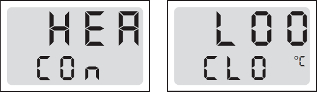
Mode 5: External Closed-Loop Control via External Interface
When done correctly, this is the most accurate and precise mode of operation for the HOTWIND SYSTEM. For this to function, the following is required:
In this mode, the percentage power at which the unit operates will be proportional to the control signal supplied to the HOTWIND SYSTEM. The external controls function to close the feedback loop. The external temperature controller parses the temperature reading from the measurement device, compares that reading to its set point, and sends an appropriate control signal to the HOTWIND SYSTEM to maintain the required temperature. As an external temperature measurement device is used, it can be placed precisely where temperature is most critical, yielding the best possible results. To operate the HOTWIND SYSTEM in this mode, enter the setup menu and set HEA to COn and LOO to OPE. See below: 
Conclusion
The best mode of operation for you will depend on your application and its requirements. If you need help determining if the HOTWIND SYSTEM is the appropriate tool, or which mode of operation you should be using give your technical sales representative a call. They’ll ask questions about your application and then recommend the best solution.
For more information on control loops, please refer to the article “Temperature Control of Air Heaters”. Comments are closed.
|

|
STANMECH Technologies Inc.
944 Zelco Drive Burlington ON L7L 4Y3 | 1-888-438-6324 | [email protected] Terms of Use Privacy Terms and Conditions of Sale Warranty Policies |
|
Proud Member of: